
Page 403 - Compression Machinery for Oil and Gas
P. 403
Upstream Compression Applications Chapter 8 381
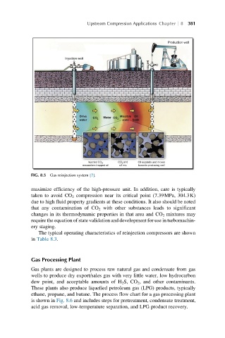
Production well
Injection well
Drive Miscible Oil
Water CO 2
CO 2
water zone bank
and Oil expands and moves
Injected CO 2
CO 2
encounters trapped oil oil mix towards producing well
FIG. 8.5 Gas reinjection system [7].
maximize efficiency of the high-pressure unit. In addition, care is typically
taken to avoid CO 2 compression near its critical point (7.39MPa, 304.3K)
due to high fluid property gradients at these conditions. It also should be noted
that any contamination of CO 2 with other substances leads to significant
changes in its thermodynamic properties in that area and CO 2 mixtures may
require the equation of state validation and development for use in turbomachin-
ery staging.
The typical operating characteristics of reinjection compressors are shown
in Table 8.3.
Gas Processing Plant
Gas plants are designed to process raw natural gas and condensate from gas
wells to produce dry export/sales gas with very little water, low hydrocarbon
dew point, and acceptable amounts of H 2 S, CO 2 , and other contaminants.
These plants also produce liquefied petroleum gas (LPG) products, typically
ethane, propane, and butane. The process flow chart for a gas processing plant
is shown in Fig. 8.6 and includes steps for pretreatment, condensate treatment,
acid gas removal, low-temperature separation, and LPG product recovery.