
Page 205 - Computational Modeling in Biomedical Engineering and Medical Physics
P. 205
194 Computational Modeling in Biomedical Engineering and Medical Physics
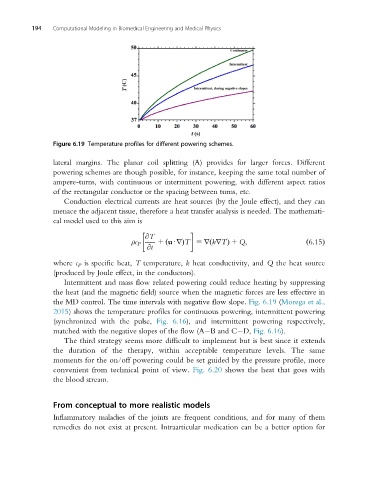
Figure 6.19 Temperature profiles for different powering schemes.
lateral margins. The planar coil splitting (A) provides for larger forces. Different
powering schemes are though possible, for instance, keeping the same total number of
ampere-turns, with continuous or intermittent powering, with different aspect ratios
of the rectangular conductor or the spacing between turns, etc.
Conduction electrical currents are heat sources (by the Joule effect), and they can
menace the adjacent tissue, therefore a heat transfer analysis is needed. The mathemati-
cal model used to this aim is
@T
ρc P 1 uUrÞT 5 r krTÞ 1 Q; ð6:15Þ
ð
@t
ð
where c P is specific heat, T temperature, k heat conductivity, and Q the heat source
(produced by Joule effect, in the conductors).
Intermittent and mass flow related powering could reduce heating by suppressing
the heat (and the magnetic field) source when the magnetic forces are less effective in
the MD control. The time intervals with negative flow slope. Fig. 6.19 (Morega et al.,
2015) shows the temperature profiles for continuous powering, intermittent powering
(synchronized with the pulse, Fig. 6.16), and intermittent powering respectively,
matched with the negative slopes of the flow (A B and C D, Fig. 6.16).
The third strategy seems more difficult to implement but is best since it extends
the duration of the therapy, within acceptable temperature levels. The same
moments for the on/off powering could be set guided by the pressure profile, more
convenient from technical point of view. Fig. 6.20 shows the heat that goes with
the blood stream.
From conceptual to more realistic models
Inflammatory maladies of the joints are frequent conditions, and for many of them
remedies do not exist at present. Intraarticular medication can be a better option for