
Page 84 - Computational Modeling in Biomedical Engineering and Medical Physics
P. 84
72 Computational Modeling in Biomedical Engineering and Medical Physics
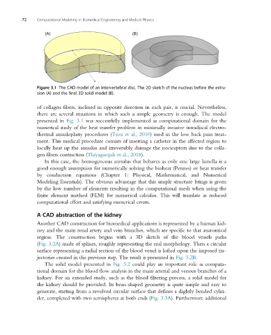
Figure 3.1 The CAD model of an intervertebral disc. The 2D sketch of the nucleus before the extru-
sion (A) and the final 3D solid model (B).
of collagen fibers, inclined in opposite direction in each pair, is crucial. Nevertheless,
there are several situations in which such a simple geometry is enough. The model
presented in Fig. 3.1 was successfully implemented as computational domain for the
numerical study of the heat transfer problem in minimally invasive intradiscal electro-
thermal annuloplasty procedures (Tsou et al., 2010) used in the low back pain treat-
ment. This medical procedure consists of inserting a catheter in the affected region to
locally heat up the annulus and irreversibly damage the nociceptors due to the colla-
gen fibers contraction (Thiyagarajah et al., 2018).
In this case, the homogeneous annulus that behaves as only one large lamella is a
good enough assumption for numerically solving the bioheat (Pennes) or heat transfer
by conduction equations (Chapter 1: Physical, Mathematical, and Numerical
Modeling Essentials). The obvious advantage that this simple structure brings is given
by the low number of elements resulting in the computational mesh when using the
finite element method (FEM) for numerical calculus. This will translate as reduced
computational effort and satisfying numerical errors.
A CAD abstraction of the kidney
Another CAD construction for biomedical applications is represented by a human kid-
ney and the main renal artery and vein branches, which are specific to that anatomical
region. The construction begins with a 3D sketch of the blood vessels paths
(Fig. 3.2A) made of splines, roughly representing the real morphology. Then a circular
surface representing a radial section of the blood vessel is lofted upon the imposed tra-
jectories created in the previous step. The result is presented in Fig. 3.2B.
The solid model presented in Fig. 3.2 could play an important role as computa-
tional domain for the blood flow analysis in the main arterial and venous branches of a
kidney. For an extended study, such as the blood filtering process, a solid model for
the kidney should be provided. Its bean-shaped geometry is quite simple and easy to
generate, starting from a revolved circular surface that defines a slightly bended cylin-
der, completed with two semispheres at both ends (Fig. 3.3A). Furthermore additional