
Page 191 -
P. 191
5.1 / SEMICONDUCTOR MAIN MEMORY 161
The other distinguishing characteristic of RAM is that it is volatile. A RAM
must be provided with a constant power supply. If the power is interrupted, then the
data are lost.Thus, RAM can be used only as temporary storage.The two traditional
forms of RAM used in computers are DRAM and SRAM.
DYNAMIC RAM RAM technology is divided into two technologies: dynamic and
static. A dynamic RAM (DRAM) is made with cells that store data as charge on
capacitors. The presence or absence of charge in a capacitor is interpreted as a bi-
nary 1 or 0. Because capacitors have a natural tendency to discharge, dynamic
RAMs require periodic charge refreshing to maintain data storage. The term
dynamic refers to this tendency of the stored charge to leak away, even with power
continuously applied.
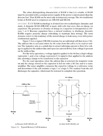
Figure 5.2a is a typical DRAM structure for an individual cell that stores 1 bit.
The address line is activated when the bit value from this cell is to be read or writ-
ten. The transistor acts as a switch that is closed (allowing current to flow) if a volt-
age is applied to the address line and open (no current flows) if no voltage is present
on the address line.
For the write operation, a voltage signal is applied to the bit line; a high voltage
represents 1, and a low voltage represents 0. A signal is then applied to the address
line, allowing a charge to be transferred to the capacitor.
For the read operation, when the address line is selected, the transistor turns
on and the charge stored on the capacitor is fed out onto a bit line and to a sense
amplifier. The sense amplifier compares the capacitor voltage to a reference value
and determines if the cell contains a logic 1 or a logic 0. The readout from the cell
discharges the capacitor, which must be restored to complete the operation.
dc voltage
Address line
T 3 T 4
C 1 C 2
T 5 T 6
Transistor
Storage
capacitor
T 1 T 2
Bit line Ground
B Ground
Bit line Bit line
Address
B B
line
(a) Dynamic RAM (DRAM) cell (b) Static RAM (SRAM) cell
Figure 5.2 Typical Memory Cell Structures