
Page 160 -
P. 160
3.5 Pyramids and wavelets 139
-½ -½ L 0
½ ½ L 0
¼ ¼ H 0 -¼ -¼ H 0
-½ -½ L 1
½ ½ L 1
¼ ¼ H 1 -¼ -¼ H 1
L 2 L 2
(a) (b)
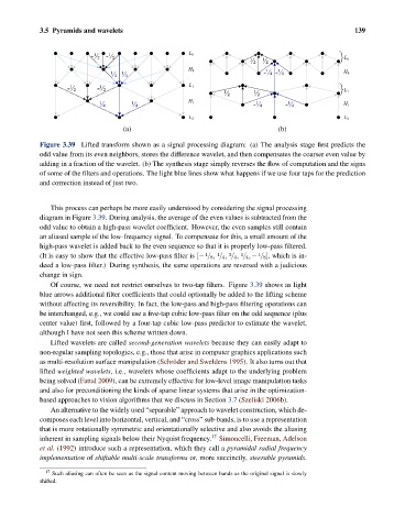
Figure 3.39 Lifted transform shown as a signal processing diagram: (a) The analysis stage first predicts the
odd value from its even neighbors, stores the difference wavelet, and then compensates the coarser even value by
adding in a fraction of the wavelet. (b) The synthesis stage simply reverses the flow of computation and the signs
of some of the filters and operations. The light blue lines show what happens if we use four taps for the prediction
and correction instead of just two.
This process can perhaps be more easily understood by considering the signal processing
diagram in Figure 3.39. During analysis, the average of the even values is subtracted from the
odd value to obtain a high-pass wavelet coefficient. However, the even samples still contain
an aliased sample of the low-frequency signal. To compensate for this, a small amount of the
high-pass wavelet is added back to the even sequence so that it is properly low-pass filtered.
3
1
1
1
(It is easy to show that the effective low-pass filter is [− / 8, / 4, / 4, / 4, − / 8], which is in-
1
deed a low-pass filter.) During synthesis, the same operations are reversed with a judicious
change in sign.
Of course, we need not restrict ourselves to two-tap filters. Figure 3.39 shows as light
blue arrows additional filter coefficients that could optionally be added to the lifting scheme
without affecting its reversibility. In fact, the low-pass and high-pass filtering operations can
be interchanged, e.g., we could use a five-tap cubic low-pass filter on the odd sequence (plus
center value) first, followed by a four-tap cubic low-pass predictor to estimate the wavelet,
although I have not seen this scheme written down.
Lifted wavelets are called second-generation wavelets because they can easily adapt to
non-regular sampling topologies, e.g., those that arise in computer graphics applications such
as multi-resolution surface manipulation (Schr¨ oder and Sweldens 1995). It also turns out that
lifted weighted wavelets, i.e., wavelets whose coefficients adapt to the underlying problem
being solved (Fattal 2009), can be extremely effective for low-level image manipulation tasks
and also for preconditioning the kinds of sparse linear systems that arise in the optimization-
based approaches to vision algorithms that we discuss in Section 3.7 (Szeliski 2006b).
An alternative to the widely used “separable” approach to wavelet construction, which de-
composes each level into horizontal, vertical, and “cross” sub-bands, is to use a representation
that is more rotationally symmetric and orientationally selective and also avoids the aliasing
inherent in sampling signals below their Nyquist frequency. 17 Simoncelli, Freeman, Adelson
et al. (1992) introduce such a representation, which they call a pyramidal radial frequency
implementation of shiftable multi-scale transforms or, more succinctly, steerable pyramids.
17 Such aliasing can often be seen as the signal content moving between bands as the original signal is slowly
shifted.