Page 156 - Corrosion Engineering Principles and Practice
P. 156

130   C h a p t e r   5     C o r r o s i o n   K i n e t i c s   a n d   A p p l i c a t i o n s   o f   E l e c t r o c h e m i s t r y    131


                     0                                                    0.09
                                                                          0.08
                     –5
                                                                          0.07
                    –10                                                   0.06
                   Potential (mV)  –15                                    0.05  Current (uA)

                                                                          0.04
                    –20                                                   0.03
                                                     Decrease in Current  0.02
                    –25                              Band Width Indicates
                                                     Decrease in General  0.01
                                                      Corrosion Activity.
                    –30                                                   0
                                                     01:24:57
                                                                   02:05:19
                                                              01:53:12
                                                          01:37:03
                                   00:40:20
                                       00:52:26
                                            01:04:32
                                                 01:16:38
                          00:16:08
                              00:28:14
                                                                      02:13:23
                     00:04:02
                    00:00:00 00:08:04 00:12:06 00:20:10 00:24:12 00:32:16 00:36:18 00:44:22 00:48:24 00:56:28 01:00:30 01:08:34 01:12:36 01:00:00 00:20:40 01:28:59 01:33:01 01:41:05 01:49:10 01:57:15 02:01:17 02:09:21
                                              Time
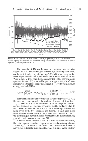
                 FIGURE 5.37  Electrochemical current noise (large band) and potential noise
                 (lower signal) in a debutanizer overhead piping obtained with the Concerto VT noise
                 system. (Courtesy of CAPCIS Ltd.)
                         The  analysis  of  EN  results  obtained  between  two  working
                      electrodes (WEs) with an imposed or naturally developing asymmetry
                      can be carried out by considering Eq. (5.27), which indicates that the
                      noise impedance of a cell (Z ) depends on the impedances of the two
                                             n
                      WEs, as well as their noise levels, represented by the power density
                      spectra (Y  i  and Y  i ) obtained by performing the analysis of noise
                                       2
                                1
                      signals with either fast Fourier transform (FFT) or with the maximum
                      entropy method (MEM).
                                                             +
                                Y   f ( )               Y  f ( ) Y  f ( )
                         Z f ) =  Y V I  f ( )  =   | ( )  2  | | ( )| Y  i 1 i 1 ( ) | ( )| Y i 2  ( )    (5.27)
                           (
                                        Z f Z f ( )|
                                                               i 2
                                                             +
                          n
                                         1
                                                           f
                                                       2
                                                                   2
                                                              Z
                                                                 f
                                                                       f
                                                   Z
                                                     f
                                                    1
                                                                2
                         For the simplest case of two WEs with the same impedance (Z  = Z )
                                                                              2
                                                                           1
                      the noise impedance is equal to the modulus of the electrode impedance
                      |Z( f  )|.  This  result  is  valid  independently  of  the  origin  of  the  noise
                      signals  (localized  or  uniform  corrosion,  bubble  evolution  due  to
                      the cathodic reaction) and the shape of the impedance plot, even if the
                      noise  levels  of  the  two  electrodes  are  different.  In  such  case,  noise
                      measurements are equivalent to impedance measurements for which
                      the external signal perturbation has been replaced by the internal noise
                      generated by the corrosion processes [24].
                         However, when the two WEs do not have the same impedance,
                      the noise impedance analysis requires a more cautious interpretation.
                      Depending on the source of the current noise the measured impedance
                      may either be that of a quiet cathode or that of a quiet anode while in
   151   152   153   154   155   156   157   158   159   160   161