
Page 211 - Corrosion Engineering Principles and Practice
P. 211
186 C h a p t e r 6 R e c o g n i z i n g t h e F o r m s o f C o r r o s i o n 187
(a)
(b)
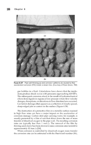
FIGURE 6.37 Pipe wall thinning (a) and corrosion patterns (b) caused by flow
accelerated corrosion (FAC) inside a steam line. (Courtesy of Russ Green, TMI)
gas bubbles in a fluid. Calculations have shown that the implo-
sions produce shock waves with pressures approaching 420 MPa.
The subsequent corrosion attack is the result of hydromechanical
effects from liquids in regions of low pressure where flow-velocity
changes, disruptions, or alterations in flow direction have occurred.
Cavitation damage often appears as a collection of closely spaced,
sharp-edged pits or craters on the surface (Figure 6.38).
The destruction of a protective film on a metallic surface exposed
to high flow rates can have a major impact on the acceleration of
corrosion damage. Carbon steel pipe carrying water, for example, is
usually protected by a film of rust that slows down the rate of mass
transfer of dissolved oxygen to the pipe wall. The resulting corrosion
rates are typically less than 1 mm/y. The removal of the film by
flowing sand slurry has been shown to raise corrosion rates tenfold to
approximately 10 mm/y [26].
When corrosion is controlled by dissolved oxygen mass transfer
the corrosion rate can be estimated with the Sherwood number (Sh),