
Page 64 - Corrosion Engineering Principles and Practice
P. 64
44 C h a p t e r 3 C o r r o s i o n E l e c t r o c h e m i s t r y 45
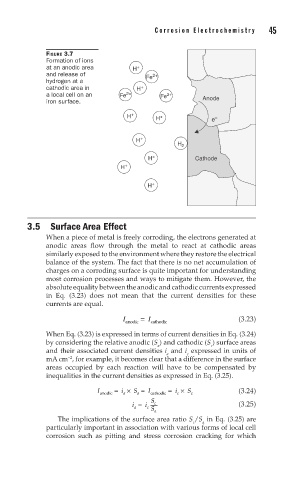
FIGURE 3.7
Formation of ions
at an anodic area H +
and release of Fe 2+
hydrogen at a
cathodic area in H +
a local cell on an Fe 2+ Fe 2+ Anode
iron surface.
H + H + e –
H +
H 2
H + Cathode
H +
H +
3.5 Surface Area Effect
When a piece of metal is freely corroding, the electrons generated at
anodic areas flow through the metal to react at cathodic areas
similarly exposed to the environment where they restore the electrical
balance of the system. The fact that there is no net accumulation of
charges on a corroding surface is quite important for understanding
most corrosion processes and ways to mitigate them. However, the
absolute equality between the anodic and cathodic currents expressed
in Eq. (3.23) does not mean that the current densities for these
currents are equal.
I anodic = I cathodic (3.23)
When Eq. (3.23) is expressed in terms of current densities in Eq. (3.24)
by considering the relative anodic (S ) and cathodic (S ) surface areas
c
a
and their associated current densities i and i expressed in units of
a
c
mA cm , for example, it becomes clear that a difference in the surface
−2
areas occupied by each reaction will have to be compensated by
inequalities in the current densities as expressed in Eq. (3.25).
I anodic = i × S = I cathodic = i × S (3.24)
c
c
a
a
S
i = i c S c a (3.25)
a
The implications of the surface area ratio S /S in Eq. (3.25) are
c
a
particularly important in association with various forms of local cell
corrosion such as pitting and stress corrosion cracking for which