
Page 128 - DSP Integrated Circuits
P. 128
Problems 113
transversal FIR filter of the type shown in Figure 3.22. The length of the
filter isN= 12 and the sample rate is 8 kHz. Determine the arithmetic work
load for the adaptive filters.
3.21 Draw a block diagram for the RLS lattice filter for N = 4.
3.22 Show that
3.23 Show that the DFT for N = 8 can be computed by essentially using two FFTs
with AT =4.
3.24 Identify the complex constants in the FFT in Figure 3.23.
3.25 Derive the signal-flow graph for the FFT, with N = 4, using the decimation-
in-frequency algorithm. What is the relationship between the decimation-in-
time and decimation-in-frequency algorithms?
3.26 Show that an IDFT can be computed by using a DFT algorithm, by first
interchanging the real and imaginary parts of the sequence, performing the
DFT, and finally interchanging the real and imaginary parts of the
intermediate result.
3.27 Show that the DFT of two real (or imaginary) sequences can be computed
simultaneously by only one FFT.
3.28 Determine the available time for computing the FFT in the FFT coprocessor
if the I/O operations are overlapped with the FFT computation.
3.29 In a transform coding system for images, the DCT-frequency components are
computed and their values are represented with different accuracy—number
of bits—to reduce the amount of data. However, the zero-frequency content of
most images is very large. Hence, if this component contributes an error to
the nonzero frequency components, then the image will be inefficiently coded
or even distorted. Determine which of the different DCTs can be used in such
an application.
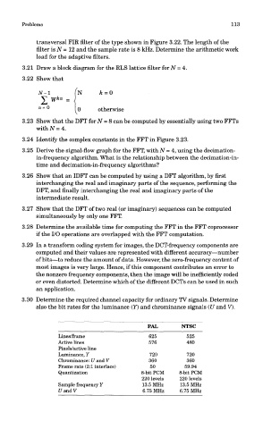
3.30 Determine the required channel capacity for ordinary TV signals. Determine
also the bit rates for the luminance (Y) and chrominance signals (U and V).
PAL NTSC
Lines/frame 625 525
Active lines 576 480
Pixels/active line
Luminance, Y 720 720
Chrominance: U and V 360 360
Frame rate (2:1 interlace) 50 59.94
Quantization 8-bit PCM 8-bit PCM
220 levels 220 levels
Sample frequency Y 13.5 MHz 13.5 MHz
UandV 6.75 MHz 6.75 MHz