
Page 132 - DSP Integrated Circuits
P. 132
4.2 FIR Filters 117
or
A corresponding function, Hft a, can also be denned for an FIR filter with anti-
symmetric impulse response.
or
Even-order FIR filters with antisymmetric impulse responses are used to real-
ize, for example, Hilbert transformers and differentiators [17,18].
4.2.2 Design of Linear-Phase FIR Filters
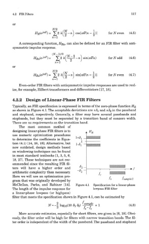
Typically, an FIR specification is expressed in terms of the zero-phase function HR
as shown in Figure 4.1. The acceptable deviations are ±di and ±82 in the passband
and stopband, respectively. Generally, a filter may have several passbands and
stopbands, but they must be separated by a transition band of nonzero width.
There are no requirements on the transition band.
The most common method of
designing linear-phase FIR filters is to
use numeric optimization procedures
to determine the coefficients in Equa-
tion (4.1) [14, 16, 18]. Alternative, but
now outdated, design methods based
on windowing techniques can be found
in most standard textbooks [1, 3, 5, 6,
18, 27]. These techniques are not rec-
ommended since the resulting FIR fil-
ters will have a higher order and
arithmetic complexity than necessary.
Here we will use an optimization pro-
gram that was originally developed by
McClellan, Parks, and Rabiner [14]. Figure 4.1 Specification for a linear-phase
The length of the impulse response for lowpass FIR filter
a linear-phase lowpass (or highpass)
filter that meets the specification shown in Figure 4.1, can be estimated by
More accurate estimates, especially for short filters, are given in [6,18]. Obvi-
ously, the filter order will be high for filters with narrow transition bands. The fil-
ter order is independent of the width of the passband. The passband and stopband