
Page 135 - DSP Integrated Circuits
P. 135
120 Chapter 4 Digital Filters
4.2.3 Half-Band FIR Filters
Many DSP schemes exploit the fact that a large number of values in the impulse
response of certain types of FIR filters are zero. The required number of arithmetic
operations can therefore be reduced for such niters since it is unnecessary to per-
form multiplications by coefficients that are zero.
Theorem 4.1
If the zero-phase function of a lowpass FIR filter is antisymmetric with
respect to 7i/2, i.e.,
then every other coefficient in the impulse response is zero except for the
one in the center, which is 0.5.
Such filters are called half-band FIR filters, since the bandwidth is about half of the
whole frequency band. The symmetry implies that the relation between the cutoff
angle and stopband angle is co cT + CD ST = n, and that the passband and stopband
deviations §i and 5% are equal. Hence, if a large stopband attenuation is required,
then the passband must have a small ripple and vice versa. This means that the
smallest of the ripple factors will determine the filter order. The reduction in the
number of arithmetic operations is significant although the required filter order
will, in practice, be slightly higher than that for a corresponding linear-phase filter.
2
The (normalized) zero-phase function isH^Ce^ ) = 0.5, i.e., the attenuation is 6 dB.
Only even-order (N = odd) half-band, lowpass FIR filters are of interest since
the coefficients are nonzero in odd-order filters.
EXAMPLE 4.2
Determine the impulse response for a half-band FIR filter that meets the following
specification: f c = 400 kHz, f s = 600 kHz, fsample = 2 MHz, and A mi n = 60 dB which
corresponds to ^2 ~ 0.001. Determine also the ripple in the passband.
Due to the symmetry requirements, we must have
Using Equation (4.9) we estimate the ripple in the passband to be
and the required filter length, according to Equation (4.8), to be
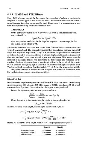
Hence, we select the filter length with N = 35. The program remez yields:
Band 1 Band 2
Lower band edge 0.00000000 0.30000000
Upper band edge 0.20000000 0.50000000
Desired value 1.00000000 0.00000000