
Page 140 - DSP Integrated Circuits
P. 140
4.3 Fir Filter Structures 125
This structure is called a direct form linear-phase FIR structure since the
phase response is independent of the coefficient values.
Even-order (N = odd) FIR filters are often preferred since the group delay is an
integer multiple of the sample period. The number of multiplications is (N + l)/2 for
N = odd and N/2 for N = even. Thus, the number of multiplications is reduced sig-
nificantly compared with the direct form, but the number of additions remains the
same. Subtracters are used instead of adders if the impulse response is antisym-
metric.
A major drawback is that the group delay for linear-phase FIR filters is often
too large to be useful in many applications. The FIR filter previously discussed
has, according to Equation (4.2), the group delay
Using the transposition theorem a transposed direct form linear-phase FIR
structure can be derived from the signal-flow graph in Figure 4.7. The number of
multiplications and additions remains the same. The signal levels are slightly
worse compared with the linear-phase direct form structure.
The number of arithmetic operations is further reduced in linear-phase, half-
band filters. Each zero-valued coefficient makes one multiplication and one addi-
tion redundant. The number of multiplications and additions is reduced signifi-
cantly compared with the direct form linear-phase FIR structure.
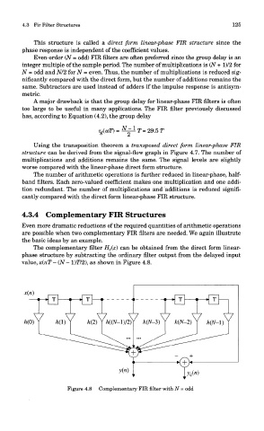
4.3.4 Complementary FIR Structures
Even more dramatic reductions of the required quantities of arithmetic operations
are possible when two complementary FIR filters are needed. We again illustrate
the basic ideas by an example.
The complementary filter H c(z) can be obtained from the direct form linear-
phase structure by subtracting the ordinary filter output from the delayed input
value,x(nT-(N- l)T/2), as shown in Figure 4.8.
Figure 4.8 Complementary FIR filter with N = odd