
Page 143 - DSP Integrated Circuits
P. 143
128 Chapter 4 Digital Filters
FIR filters. However, it is not possible to have exactly linear-phase IIR filters. For-
tunately, neither is it usually necessary. It is only necessary to have a phase
response that is sufficiently linear in the passband. In such cases it is often sim-
pler and more efficient to cascade two IIR filters than to use a linear-phase FIR fil-
ter. One of the IIR filters is designed to meet the frequency selective requirements
while the other corrects the group delay so that the two filters combined meet the
linear-phase requirements. In some cases, it may be efficient to use a combination
of FIR and IIR filters. The improved frequency selective properties of IIR filters
are obtained at the expense of increased coefficient sensitivity and potential insta-
bility. These issues will be further discussed in Chapter 5.
4.6 SPECIFICATION OF IIR FILTERS
Frequency-selective filters are speci-
fied in the frequency domain in terms
of an acceptable deviation from the
desired behavior of the magnitude or
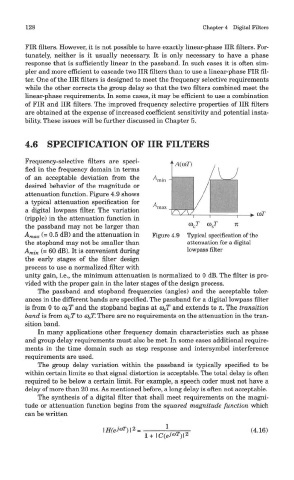
attenuation function. Figure 4.9 shows
a typical attenuation specification for
a digital lowpass filter. The variation
(ripple) in the attenuation function in
the passband may not be larger than
A max (= 0.5 dB) and the attenuation in Figure 4.9 Typical specification of the
the stopband may not be smaller than attenuation for a digital
A mi n (= 60 dB). It is convenient during lowpass filter
the early stages of the filter design
process to use a normalized filter with
unity gain, i.e., the minimum attenuation is normalized to 0 dB. The filter is pro-
vided with the proper gain in the later stages of the design process.
The passband and stopband frequencies (angles) and the acceptable toler-
ances in the different bands are specified. The passband for a digital lowpass filter
is from 0 to co cT and the stopband begins at co sT and extends to n. The transition
band is from Q) CT to 0) ST. There are no requirements on the attenuation in the tran-
sition band.
In many applications other frequency domain characteristics such as phase
and group delay requirements must also be met. In some cases additional require-
ments in the time domain such as step response and intersymbol interference
requirements are used.
The group delay variation within the passband is typically specified to be
within certain limits so that signal distortion is acceptable. The total delay is often
required to be below a certain limit. For example, a speech coder must not have a
delay of more than 20 ms. As mentioned before, a long delay is often not acceptable.
The synthesis of a digital filter that shall meet requirements on the magni-
tude or attenuation function begins from the squared magnitude function which
can be written