
Page 148 - DSP Integrated Circuits
P. 148
4.8 Mapping of Analog Transfer Functions 133
example, different attenuation requirements in the two stopbands. Substantial
improvements in such cases are obtained using iterative methods [4, 24]. In
Example 4.4 we demonstrate the design of a bandpass filter with a more compli-
cated specification.
EXAMPLE 4.4
In this example we demonstrate the synthesis of a digital IIR filter, using a so-
1
called pole placer program [4, 24], that meets the following specification:
The band edges are
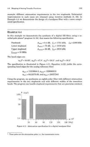
The specification is illustrated in Figure 4.11. Equation (4.22) yields the corre-
sponding band edges for the analog reference filter:
Using the program, we synthesize an eighth-order filter with different attenuation
requirements in the two stopbands and with different widths of the transition
bands. The program can handle stopband requirements that are piecewise constant
Figure 4.11 Attenuation specification for a digital bandpass filter
1
- These poles are the attenuation poles, i.e., the transmission zeros.