
Page 149 - DSP Integrated Circuits
P. 149
134 Chapter 4 Digital Filters
and maximally flat or have equal ripple in the passband. In this case, we select
equal ripple in the passband in order to minimize the filter order. We get
Poles Zeros
Next we can map the poles and zeros of the analog filter to the z-plane using the
inverse of Equation (4.21):
We get the following poles:
and zeros:
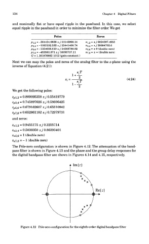
The Pole-zero configuration is shown in Figure 4.12. The attenuation of the band-
pass filter is shown in Figure 4.13 and the phase and the group delay responses for
the digital bandpass filter are shown in Figures 4.14 and 4.15, respectively.
Figure 4.12 Pole-zero configuration for the eighth-order digital bandpass filter