
Page 151 - DSP Integrated Circuits
P. 151
136 Chapter 4 Digital Filters
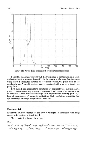
Figure 4.15 Group delay for the eighth-order digital bandpass filter
Notice the discontinuities (180°) at the frequencies of the transmission zeros,
and notice that the phase varies rapidly in the passband. Also note that the group
delay, which is measured in terms of the sample period, has peaks close to the
passband edges. A small transition band is associated with large variations in the
group delay.
Both cascade and parallel form structures are commonly used in practice. The
primary reason is that they are easy to understand and design. They are also used
as examples in most textbooks although their properties are not very good—e.g.,
lack of suppression of parasitic oscillations, high coefficient sensitivity, low
dynamic range, and high computational work load.
EXAMPLE 4.5
Realize the transfer function for the filter in Example 4.4 in cascade form using
second-order sections in direct form I.
The transfer function can be written