
Page 156 - DSP Integrated Circuits
P. 156
4.13 Transmission Lines 141
tures can be mapped to classical filter structures with lumped circuit elements and
we can make full use of the abundant knowledge of lumped element niters.
4.13 TRANSMISSION LINES
A special case of filter networks with distributed circuit elements is commensurate-
length transmission line filters in which all lines have a common electrical propa-
gation time. A lossless transmission line can be described as a two-port by the
chain matrix
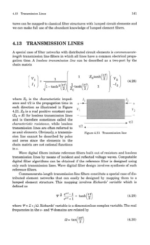
where ZQ is the characteristic imped-
ance and T/2 is the propagation time in
each direction as illustrated in Figure
4.21. ZQ is a real positive constant cure
(Zo = R) for lossless transmission lines
and is therefore sometimes called the
characteristic resistance, while lossless
transmission lines are often referred to
as unit elements. Obviously, a transmis- Figure 4.21 Transmission line
sion line cannot be described by poles
and zeros since the elements in the
chain matrix are not rational functions
ins.
Wave digital filters imitate reference filters built out of resistors and lossless
transmission lines by means of incident and reflected voltage waves. Computable
digital filter algorithms can be obtained if the reference filter is designed using
only such transmission lines. Wave digital filter design involves synthesis of such
reference filters.
Commensurate-length transmission line filters constitute a special case of dis-
tributed element networks that can easily be designed by mapping them to a
lumped element structure. This mapping involves Richards' variable which is
defined as
where f= £ +jQ. Richards' variable is a dimensionless complex variable. The real
frequencies in the s- and f-domains are related by