
Page 161 - DSP Integrated Circuits
P. 161
146 Chapter 4 Digital Filters
The corresponding wave-flow
graph is shown to the right in Fig-
ure 4.27. An open-circuit has the
reflectance
Figure 4.27 Wave-flow equivalent for a short-
The wave-flow graph for an
circuit
open-circuit is shown to the right
in Figure 4.28.
Finally, we have for the
resistive voltage source shown in
Figure 4.29:
which yields the reflected voltage
wave Figure 4.28 Wave-flow equivalent
for an open-circuit
The corresponding wave-flow graph is shown in Figure 4.29.
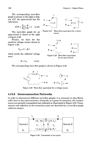
4.15.2 Interconnection Networks
In order to interconnect different wave-flow graphs, it is necessary to obey Kirch-
hoff's laws at the interconnection. Generally, at a point of connection, the incident
waves are partially transmitted and reflected as illustrated in Figure 4.30. Trans-
mission and reflection at the connection point are described by a wave-flow graph
called an adaptor.
Figure 4.30 Connection of two ports