
Page 158 - DSP Integrated Circuits
P. 158
4.14 Transmission Line Filters 143
4.14 TRANSMISSION LINE FILTERS
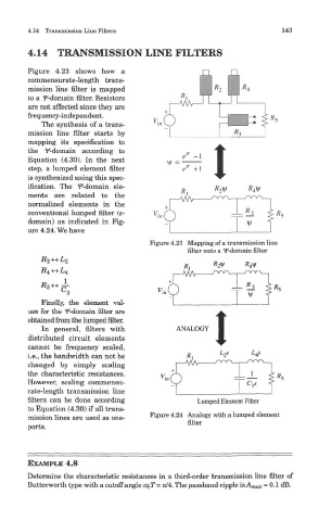
Figure 4.23 shows how a
commensurate-length trans-
mission line filter is mapped
to a f-domain filter. Resistors
are not affected since they are
frequency-independent.
The synthesis of a trans-
mission line filter starts by
mapping its specification to
the f-domain according to
Equation (4.30). In the next
step, a lumped element filter
is synthesized using this spec-
ification. The ^-domain ele-
ments are related to the
normalized elements in the
conventional lumped filter (s-
domain) as indicated in Fig-
ure 4.24. We have
Figure 4.23 Mapping of a transmission line
filter onto a f-domain filter
Finally, the element val-
ues for the f-domain filter are
obtained from the lumped filter.
In general, filters with
distributed circuit elements
cannot be frequency scaled,
i.e., the bandwidth can not be
changed by simply scaling
the characteristic resistances.
However, scaling commensu-
rate-length transmission line
filters can be done according
to Equation (4.30) if all trans-
Figure 4.24 Analogy with a lumped element
mission lines are used as one-
filter
ports.
EXAMPLE 4.8
Determine the characteristic resistances in a third-order transmission line filter of
Butterworth type with a cutoff angle 0) CT = 7t/4. The passband ripple is A max = 0.1 dB.