
Page 155 - DSP Integrated Circuits
P. 155
140 Chapter 4 Digital Filters
Historically, the rationale for developing different filter structures was the
desire for low element sensitivity. Although low sensitivity is important, the most
stringent requirement is that the structure is guaranteed to be stable. This issue
will be further discussed in Chapter 5. Properly designed wave digital filters meet
both of these requirements.
4.12 WAVE DESCRIPTIONS
Wave digital filter theory is based on a scattering parameter formalism that has
been used for a long time in microwave theory for describing networks with dis-
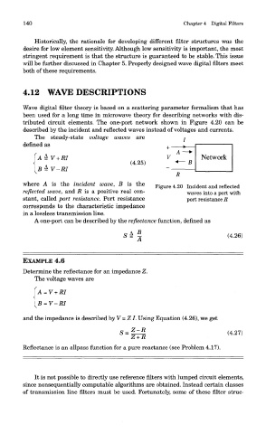
tributed circuit elements. The one-port network shown in Figure 4.20 can be
described by the incident and reflected waves instead of voltages and currents.
me steady-state voltage waves are
defined as
where A is the incident wave, B is the Figure 4.20 Incident and reflected
reflected wave, and R is a positive real con- waves into a port with
stant, called port resistance. Port resistance port resistance R
corresponds to the characteristic impedance
in a lossless transmission line.
A one-port can be described by the reflectance function, defined as
EXAMPLE 4.6
Determine the reflectance for an impedance Z.
The voltage waves are
and the impedance is described by V = Z I. Using Equation (4.26), we get
Reflectance is an allpass function for a pure reactance (see Problem 4.17).
It is not possible to directly use reference filters with lumped circuit elements,
since nonsequentially computable algorithms are obtained. Instead certain classes
of transmission line filters must be used. Fortunately, some of these filter struc-