
Page 152 - DSP Integrated Circuits
P. 152
4.9 Mapping Of Analog Filter Structures 137
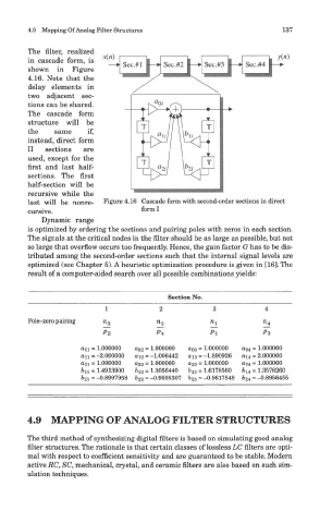
The filter, realized
in cascade form, is
shown in Figure
4.16. Note that the
delay elements in
two adjacent sec-
tions can be shared.
The cascade form
structure will be
the same if,
instead, direct form
II sections are
used, except for the
first and last half-
sections. The first
half-section will be
recursive while the
last will be nonre- Figure 4.16 Cascade form with second-order sections in direct
cursive. form I
Dynamic range
is optimized by ordering the sections and pairing poles with zeros in each section.
The signals at the critical nodes in the filter should be as large as possible, but not
so large that overflow occurs too frequently. Hence, the gain factor G has to be dis-
tributed among the second-order sections such that the internal signal levels are
optimized (see Chapter 5). A heuristic optimization procedure is given in [16]. The
result of a computer-aided search over all possible combinations yields:
Section No.
4.9 MAPPING OF ANALOG FILTER STRUCTURES
The third method of synthesizing digital filters is based on simulating good analog
filter structures. The rationale is that certain classes of lossless LC filters are opti-
mal with respect to coefficient sensitivity and are guaranteed to be stable. Modern
active RC, SC, mechanical, crystal, and ceramic filters are also based on such sim-
ulation techniques.