
Page 146 - DSP Integrated Circuits
P. 146
4.8 Mapping of Analog Transfer Functions 131
in practice only the bilinear transformation is appropriate for mapping frequency-
selective analog filters to digital filters.
The bilinear transformation is
defined as
The relation between the analog
cutoff frequency and the cutoff angle
for the digital filter is
Next, the approximation problem is
solved for the lowpass filter, giving the
analog transfer function, H(s). Note that
the phase response of the analog filter is
distorted using the bilinear transforma-
tion [1, 6, 15-18, 27]. Finally, the poles
and zeros of the analog lowpass filter
are mapped to the digital domain,
yielding the poles and zeros of the digi-
tal filter.
Details of this design procedure
can be found in many textbooks [1, 2,
4-6, 15-18, 24, 26, 271. This design
approach only solves the problem of
finding a transfer function H(z) that
satisfies the magnitude specification.
Later we will discuss methods that will
also provide good filter algorithms.
It is interesting to note that a digital
lowpass filter is transformed to a band-
pass filter which is symmetric around 7i/2
2
by the transformation z —> -z . The
transformation can be done either by
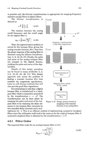
mapping the poles and zeros of the low- Figure 4.10 Design process based on
pass filter or by replacing the delay ele- mapping of the transfer
ments in the lowpass filter structure by function of an analog filter
two cascaded delay elements and a mul-
tiplication by -1. This is an efficient method of implementing symmetric bandpass
filters since the arithmetic work load is the same as for the original lowpass filter. A
2
symmetric stopband filter is obtained by the transformation z -> z .
4.8.1 Filter Order
The required filter order for an analog lowpass filter is [11]