
Page 136 - DSP Integrated Circuits
P. 136
4.2 FIR Filters 121
Band 1 Band 2
Weighting 1.00000000 1.00000000
Deviation 0.00067458 0.00067458
Deviation in dB 0.01171863 -63.41935048
* * * * Impulse Response * * * *
h(0) =0.0011523147 = h(34) h(9) =0.0000205816 =/i(25)
Ml) = 0.0000053778 = /i(33) h(W) = -0.0310922116 = M24)
h(2) = -0.0027472085 = /i(32) h(U) = -0.0000213219 = ft(23)
M3) = -0.0000047933 = 7*(31) /i(12) = 0.0525993770 = A(22)
7i(4) = 0.0057629677 = 7t(30) 7i(13) = 0.0000279603 = fc(21)
h(S) = 0.0000118490 = h(29) h(U) = -0.0991307839 = h(20)
h(6) = -0.0107343126 = h(2S) h(l5) = -0.0000262782 = /i(19)
h(7) = -0.0000127702 = h(27) h(16) = 0.3159246316 = h(lS)
h(S) = 0.0185863941 = 7i(26) 7i(17) = 0.5000310310
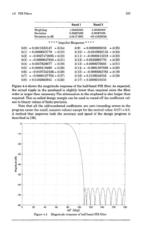
Figure 4.4 shows the magnitude response of the half-band FIR filter. As expected,
the actual ripple in the passband is slightly lower than required since the filter
order is larger then necessary. The attenuation in the stopband is also larger than
required. This so-called design margin can be used to round off the coefficient val-
ues to binary values of finite precision.
Note that all the odd-numbered coefficients are zero (rounding errors in the
program cause the small, nonzero values) except for the central value: h(l7) - 0.5.
A method that improves both the accuracy and speed of the design program is
described in [28].
Figure 4.4 Magnitude response of half-band FIR filter