
Page 134 - DSP Integrated Circuits
P. 134
4.2 FIR Filters 119
Band 1 Band 2 Band 3 Band 4 Band 5
Lower band edge 0.00000000 0.10000000 0.20000000 0.30000000 0.40000000
Upper band edge 0.05000000 0.15000000 0.25000000 0.35000000 0.50000000
Desired value 0.00000000 1.00000000 0.00000000 1.00000000 0.00000000
Weighting 1.00000000 1.00000000 1.00000000 1.00000000 10.00000000
Deviation 0.00384571 0.00384571 0.00384571 0.00384571 0.00038457
Deviation [dB] -48.30047209 0.06680713 ^48.30047209 0.06680713 -68.30047209
* * * * Impulse Response * * * *
h(0) = -0.0013347852 = h(59) h(l5) = -0.0024767997 = h(44)
/i(l) = 0.0020944327 = h(58) h(lG) = 0.0275492809 = fc(43)
h(2) = 0.0025711690 = h(57) 7i(17) = 0.0031292486 = h(42)
h(3) = -0.0064205864 = /i(56) h(l8) = 0.0214422648 = h(4l)
h(4) = 0.0002917069 = /i(55) h(l9) = 0.0060822033 = h(40)
h(5) = 0.0095955751 = h(54) h(20) = 0.0154276991 = h(39)
h(6) = 0.0010398870 = h(53) h(2l) = 0.0217612708 = h(B8)
h(l} = 0.0013729018 = fc(52) h(22) = -0.0063723040 = A(37)
h(8) = 0.0007270137 = A(51) h(23) = 0.0987030933 = h(36)
h(9) = -0.0011216574 = &(50) A(24) = -0.0168138109 = h(35)
h(W) = 0.0008927758 = fc(49) h(25) = -0.2507191136 = fc(34)
h(ll) = -0.0092173547 = /i(48) h(26) = -0.0447299558 = h(33)
h(l2) = 0.0072828894 = /i(47) h(27) = -0.0082915615 = h(32)
h(l3) = -0.0022192106 = /i(46) h(28) = -0.1105607994 = h(3l)
h(U) = -0.0463359170 = h(45) h(29) = 0.2885732985 = h(30)
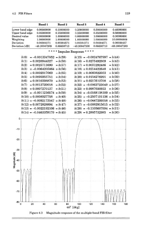
Figure 4.3 Magnitude response of the multiple-band FIR filter