
Page 192 - DSP Integrated Circuits
P. 192
4.24 Multirate Filters 177
13,19]. For example, an increase in the sampling rate by a factor 3.5 can be achieved
by first interpolating the sampling frequency by a factor seven and then decimating it
by a factor two. The interpolating and decimating lowpass niters can be combined into
a single filter. See Problem 4.32.
Note that the sampling frequencies for compact disc players and digital audio
tape recorders (DAT) have been chosen such that conversion between the two sys-
tems becomes difficult. The ratio of the two sample rates is a ratio between two very
large integers. Interpolation from 44.1 kHz (CD player) to 48 kHz (DAT) can be done
by first interpolating by a factor 160 and then decimating by a factor 147. Hence, the
sampling rate has to be interpolated to a very high rate before being decimated. This
is very expensive. However, most of the sample values in the interpolator are zero
and only one of the 147 output values needs to be computed, so the work load can be
reduced significantly. See Problem 4.34. It is possible to interpolate and decimate
with arbitrary ratios by using more advanced techniques [16,20].
4.24 MULTIRATE FILTERS
In some cases it is efficient from a computational point of view to realize an ordinary
single-rate digital filter as a multirate filter. This approach is particularly efficient to
realize filters with very narrow passbands or transition bands [1, 19, 22, 23]. Such
narrow band filters can be realized by a combination of decimation and interpolation
stages. The stages can be of either FIR or IIR type, or a combination.
Another typical application can be found in digital filter banks that are com-
monly used in telecommunication systems as well as in image and speech coders.
4.25 INTERPOLATOR—CASE STUDY 3
As the third case study, we choose an application with an interpolating wave digi-
tal filter. Assume that the sampling frequency of the signal discussed in Example
4.15 shall instead be increased from 1.6 to 6.4 MHz. This can be done by interpo-
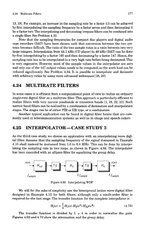
lating the sampling rate in two steps, as shown in Figure. 4.68. The interpolator
has been cascaded with an allpass filter for equalizing the group delay.
Figure 4.68 Interpolating WDF
We will for the sake of simplicity use the bireciprocal lattice wave digital filter
designed in Example 4.12 for both filters, although only a ninth-order filter is
required for the last stage. The transfer function for the complete interpolator is
The transfer function is divided by L = 4 in order to normalize the gain.
Figures 4.69 and 4.70 show the attenuation and the group delay.