
Page 187 - DSP Integrated Circuits
P. 187
172 Chapter 4 Digital Filters
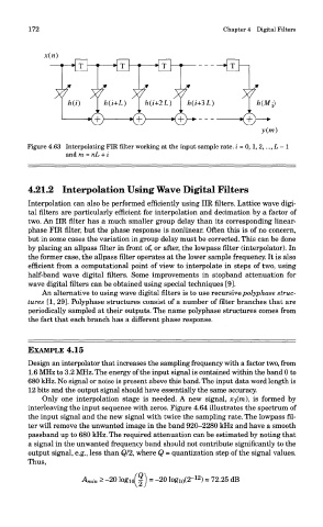
Figure 4.63 Interpolating FIR filter working at the input sample rate, i = 0,1, 2,..., L - 1
and m = nL + i
4.21.2 Interpolation Using Wave Digital Filters
Interpolation can also be performed efficiently using IIR filters. Lattice wave digi-
tal filters are particularly efficient for interpolation and decimation by a factor of
two. An IIR filter has a much smaller group delay than its corresponding linear-
phase FIR filter, but the phase response is nonlinear. Often this is of no concern,
but in some cases the variation in group delay must be corrected. This can be done
by placing an allpass filter in front of, or after, the lowpass filter (interpolator). In
the former case, the allpass filter operates at the lower sample frequency. It is also
efficient from a computational point of view to interpolate in steps of two, using
half-band wave digital filters. Some improvements in stopband attenuation for
wave digital filters can be obtained using special techniques [9].
An alternative to using wave digital filters is to use recursive polyphase struc-
tures [I, 29]. Polyphase structures consist of a number of filter branches that are
periodically sampled at their outputs. The name polyphase structures comes from
the fact that each branch has a different phase response.
EXAMPLE 4.15
Design an interpolator that increases the sampling frequency with a factor two, from
1.6 MHz to 3.2 MHz. The energy of the input signal is contained within the band 0 to
680 kHz. No signal or noise is present above this band. The input data word length is
12 bits and the output signal should have essentially the same accuracy.
Only one interpolation stage is needed. A new signal, x-\(m\ is formed by
interleaving the input sequence with zeros. Figure 4.64 illustrates the spectrum of
the input signal and the new signal with twice the sampling rate. The lowpass fil-
ter will remove the unwanted image in the band 920—2280 kHz and have a smooth
passband up to 680 kHz. The required attenuation can be estimated by noting that
a signal in the unwanted frequency band should not contribute significantly to the
output signal, e.g., less than Q/2, where Q = quantization step of the signal values.
Thus,