
Page 186 - DSP Integrated Circuits
P. 186
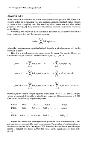
4.21 Interpolation With an Integer Factor L                          171


        EXAMPLE 4.14
        Show that an FIR interpolator can be decomposed into L parallel FIR niters that
        operate at the input sampling rate and produce a combined output signal with an
        L times higher sampling rate. The resulting filter structures are often called
        polyphase filters [2, 3]. Also, determine the relation between the impulse responses
        of the filters.
            Generally, the output of the FIR filter is described by the convolution of the
        input sequence xi(ni) and the impulse response


        where the input sequence x\(m) is obtained from the original sequence x(n) by the
        insertion of zeros.
            Now, the original sequence is nonzero only for every Lth sample. Hence, we
        have for the output values at time instances, m,ra + l,...,ra+L — 1:


        where M^ is the largest integer equal to or less than (N - i - 1)/L. Thus, L output
        values are computed from the original input sequence. This corresponds to L FIR
        filters with the following impulse responses


            Figure 4.63 shows the final signal-flow graph for the FIR interpolator. L out-
        put samples are computed for each input sample. The number of multiplications is
        N (the same number as in the original FIR filter) but the number of operations per
        second is reduced by a factor L. Only the values in the input sequence need to be
        stored.