
Page 182 - DSP Integrated Circuits
P. 182
4.21 Interpolation With an Integer Factor L 167
Figure 4.56 shows the symbol used for depicting
the operation of interleaving L—1 zeros between each
input sample. The opposite operation of removing L-l
samples is called compression and is depicted with a
downward-pointing arrow.
The new signal, x\(m), is formed from x(ri) accord-
ing to
otherwise
The sample period for the new sequence is T\ = TIL. The Fourier transform of
x\(m) can be expressed in terms of the Fourier transform of x(ri) according to
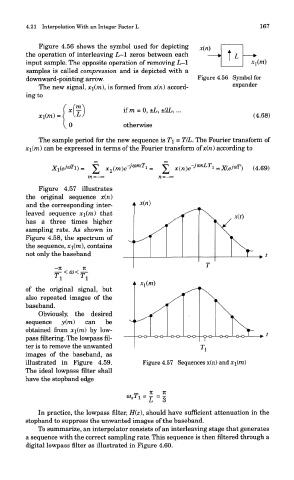
Figure 4.57 illustrates
the original sequence x(n)
and the corresponding inter-
leaved sequence xi(m) that
has a three times higher
sampling rate. As shown in
Figure 4.58, the spectrum of
the sequence, #i(ra), contains
not only the baseband
of the original signal, but
also repeated images of the
baseband.
Obviously, the desired
sequence y(m) can be
obtained from x\(m) by low-
pass filtering. The lowpass ni-
ter is to remove the unwanted
images of the baseband, as
illustrated in Figure 4.59. Figure 4.57 Sequences x(n) and x\(m)
The ideal lowpass filter shall
have the stopband edge
In practice, the lowpass filter, H(z\ should have sufficient attenuation in the
stopband to suppress the unwanted images of the baseband.
To summarize, an interpolator consists of an interleaving stage that generates
a sequence with the correct sampling rate. This sequence is then filtered through a
digital lowpass filter as illustrated in Figure 4.60.