
Page 181 - DSP Integrated Circuits
P. 181
166 Chapter 4 Digital Filters
4.20 MULTIRATE SYSTEMS
In multirate systems the sampling frequency is changed during the signal process-
ing. In most cases the sampling rates at the input and output differ. Such sam-
pling rate conversions are needed when systems with different sampling
frequencies are to be interconnected [1, 3, 13, 19, 20, 29]. In other cases the sam-
pling rate is only changed internally, while the input and output rates are the
same. This is done in order to improve the efficiency of the processing. These tech-
niques are commonly used in narrow band lowpass, highpass, and bandpass filters
[23], filter banks [3, 6, 13, 29], so-called transmultiplexors (converters between
FDM and TDM systems), and delays of a fraction of the sample interval [3, 13].
Potential advantages of multirate signal processing are reduced computational
work load, lower filter order, lower coefficient sensitivity and noise, and less strin-
gent memory requirements. Disadvantages are more complex design, aliasing and
imaging errors, and a more complex algorithm. Multirate techniques are used
today in many digital signal processing systems.
4.21 INTERPOLATION WITH AN INTEGER
FACTOR L
In many digital signal processing applications, it is necessary or computationally
desirable to change the sampling frequency without changing the information in
the signal. Generally, it is favorable to use as low a sampling rate as possible, since
the computational work load and the required numerical accuracy will be lower.
The process of increasing the sampling rate is called interpolation. The aim is to
get a new sequence corresponding to a higher sampling frequency, but with the same
informational content, i.e., with the same spectrum as the underlying analog signal.
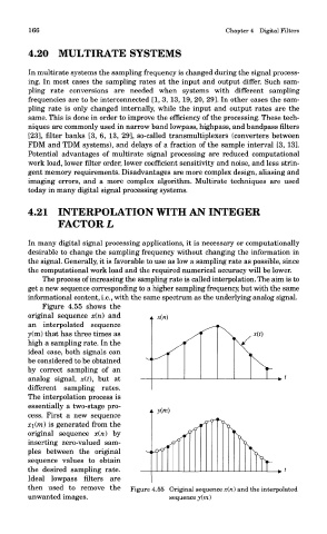
Figure 4.55 shows the
original sequence x(n) and
an interpolated sequence
y(m) that has three times as
high a sampling rate. In the
ideal case, both signals can
be considered to be obtained
by correct sampling of an
analog signal, x(f), but at
different sampling rates.
The interpolation process is
essentially a two-stage pro-
cess. First a new sequence
x\(m) is generated from the
original sequence x(ri) by
inserting zero-valued sam-
ples between the original
sequence values to obtain
the desired sampling rate.
Ideal lowpass filters are
then used to remove the Figure 4.55 Original sequence x(n) and the interpolated
unwanted images. sequence y(m)