
Page 178 - DSP Integrated Circuits
P. 178
4.19 Bireciprocal Lattice Wave Digital Filters 163
Thus, the high stopband attenuation will force the ripple in the magnitude
response to be very small for frequencies up to 170 kHz. Using the program we get
the required filter order
Lowpass lattice filters must be of odd order. We select the next higher odd integer:
N = 11. The program computes that the stopband frequency must be selected in
the range
We select f s = 228 kHz. Thus, the passband edge will, due to the inherent symme-
try, be
The passband ripple factor can be selected in the range
We select e p = 0.000173 which corresponds to the passband ripple A ma:K =
7
1.255 10~ dB and the stopband attenuation becomes A mi n = 75.239 dB. It would,
however, have been better to select a slightly higher value (i.e., a smaller design
margin in the passband) and leave a larger part for the stopband, since the sensi-
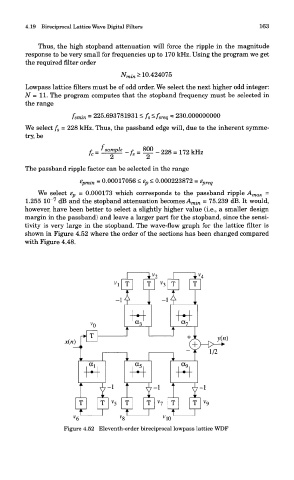
tivity is very large in the stopband. The wave-flow graph for the lattice filter is
shown in Figure 4.52 where the order of the sections has been changed compared
with Figure 4.48.
Figure 4.52 Eleventh-order bireciprocal lowpass lattice WDF