
Page 180 - DSP Integrated Circuits
P. 180
4.19 Bireciprocal Lattice Wave Digital Filters 165
x10' 7
1.51 1 1 1 n n 1 1 1
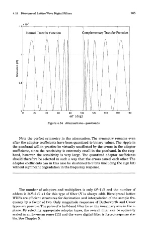
Normal Transfer Function C omplementary Transfer Function
Q\I i \i i \i i y ii 1 1 11 1 y i \i i \i i A
0 20 40 60 80 100 120 140 160 180
cor [deg]
Figure 4.54 Attenuations—passbands
Note the perfect symmetry in the attenuation. The symmetry remains even
after the adaptor coefficients have been quantized to binary values. The ripple in
the passband will in practice be virtually unaffected by the errors in the adaptor
coefficients, since the sensitivity is extremely small in the passband. In the stop-
band, however, the sensitivity is very large. The quantized adaptor coefficients
should therefore be selected in such a way that the errors cancel each other. The
adaptor coefficients can in this case be shortened to 9 bits (including the sign bit)
without significant degradation in the frequency response.
The number of adaptors and multipliers is only (N-l)/2 and the number of
adders is 3(JV-l)/2 +1 for this type of filter (N is always odd). Bireciprocal lattice
WDFs are efficient structures for decimation and interpolation of the sample fre-
quency by a factor of two. Only magnitude responses of Butterworth and Cauer
types are possible. The poles of a half-band filter lie on the imaginary axis in the z-
plane. By selecting appropriate adaptor types, the overall filter can be optimally
scaled in an L°o-norm sense [11] and the wave digital filter is forced-response sta-
ble. See Chapter 5.