
Page 184 - DSP Integrated Circuits
P. 184
4.21 Interpolation With an Integer Factor L 169
Box 4.1. Pseudo-code for the interpolator.
4.21.1 Interpolation Using FIR Filters
Interpolation with an integer factor can be accomplished by using FIR niters. In
principle the interpolator filter is a lowpass filter that removes the unwanted
images of the baseband. If the original signal is bandlimited to cooT < n, then the
band o^T to TC will appear as bands between the images. These bands will not con-
tain any energy from the input signal. Hence, the attenuation in these bands may
be unspecified. This relaxation of the stopband requirement can be exploited to
reduce the filter order.
A major drawback of higher-order FIR filters is the large group delay, approx-
imately half the filter length. A large group delay is unacceptable in many applica-
tions. It is also associated with large memory requirement. Another drawback of
FIR filters is the high computational work load, but this can be reduced by elimi-
nating multiplications with signal values that are zero. This reduces the number
of multiplications by a factor L [1]. It is also favorable to perform the interpolation
in several steps of two. The lowpass filters then become half-band filters. Almost
half the coefficients in a half-band filter are zero.
EXAMPLE 4.13
Determine the requirements for an FIR filter in an interpolator that interpolates
the sampling frequency with a factor five. The input signal is bandlimited to 0 to
Ti/2, and the sampling frequency is 100 kHz. Assume that image bands shall be
attenuated by at least 60 dB and the passband ripple must be less than 0.5 dB.
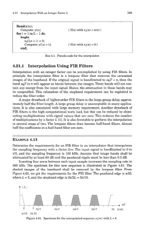
Inserting four zeros between each input sample increases the sampling rate to
500 kHz. The spectrum for this new sequence is illustrated in Figure 4.61. The
shaded images of the baseband shall be removed by the lowpass filter. From
Figure 4.61, we get the requirements for the FIR filter. The passband edge is 7C/2L
where L = 5, and the stopband edge is 371/2L = 371/10.
Figure 4.61 Spectrum for the interpolated sequence x\(m) with L = 5