
Page 189 - DSP Integrated Circuits
P. 189
174 Chapter 4 Digital Filters
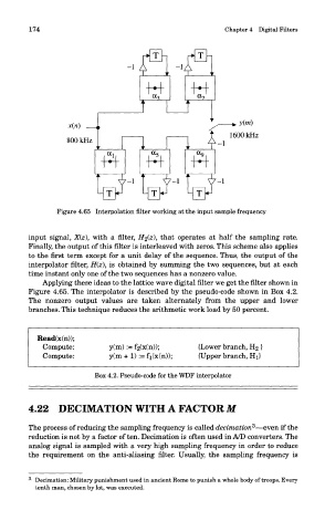
Figure 4.65 Interpolation filter working at the input sample frequency
input signal, X(z), with a filter, H2(z\ that operates at half the sampling rate.
Finally, the output of this filter is interleaved with zeros. This scheme also applies
to the first term except for a unit delay of the sequence. Thus, the output of the
interpolator filter, H(z), is obtained by summing the two sequences, but at each
time instant only one of the two sequences has a nonzero value.
Applying these ideas to the lattice wave digital filter we get the filter shown in
Figure 4.65. The interpolator is described by the pseudo-code shown in Box 4.2.
The nonzero output values are taken alternately from the upper and lower
branches. This technique reduces the arithmetic work load by 50 percent.
Box 4.2. Pseudo-code for the WDF interpolator
4.22 DECIMATION WITH A FACTOR M
3
The process of reducing the sampling frequency is called decimation —even if the
reduction is not by a factor of ten. Decimation is often used in A/D converters. The
analog signal is sampled with a very high sampling frequency in order to reduce
the requirement on the anti-aliasing filter. Usually, the sampling frequency is
3
- Decimation: Military punishment used in ancient Rome to punish a whole body of troops. Every
tenth man, chosen by lot, was executed.