
Page 173 - DSP Integrated Circuits
P. 173
158 Chapter 4 Digital Filters
antenna to the receiver in a radar. Ideally, no signal is directed from the transmit-
ter to the receiver. The circulator has the property of "circulating" an incident
wave to the next port.
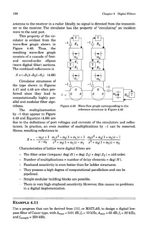
This property of the cir-
culator is evident from the
wave-flow graph shown in
Figure 4.48. Thus, the
resulting wave-flow graph
consists of a cascade of first-
and second-order allpass
(wave digital filter) sections.
The combined reflectance is
S = (-S l)(-S 2)(-S 3) (4.66)
Circulator structures of
the type shown in Figures
4.47 and 4.48 are often pre-
ferred since they lead to
computationally highly par-
allel and modular filter algo-
rithms. Figure 4.48 Wave-flow graph corresponding to the
The multiplicatuation reference structure in Figure 4.46
by -1 that appear in Figure
4.48 and Equation (4.66) are
due to the definitions of port voltages and currents of the circulators and reflec-
tances. In practice, an even number of multiplications by —1 can be removed.
Hence, resulting reflectance is
Characteristics of lattice wave digital filters are
4- The filter order (lowpass): deg{ H} = deg{ Z]j + deg{ Z^ } = odd order.
4= Number of multiplications = number of delay elements = deg{ H}.
4= Passband sensitivity is even better than for ladder structures.
4- They possess a high degree of computational parallelism and can be
pipelined.
4= Simple modular building blocks are possible.
= There is very high stopband sensitivity. However, this causes no problems
in a digital implementation.
EXAMPLE 4.11
Use a program that can be derived from [11], or MATLAB, to design a digital low-
pass filter of Cauer type, withA^^ = 0.01 dB,f c = 10 kHz,A mj n = 65 dB,/ s = 20 kHz,
and /'sample = 25 ° kH Z.