
Page 171 - DSP Integrated Circuits
P. 171
156 Chapter 4 Digital Filters
Figure 4.45 Richards' structure—cascaded unit elements
EXAMPLE 4.10
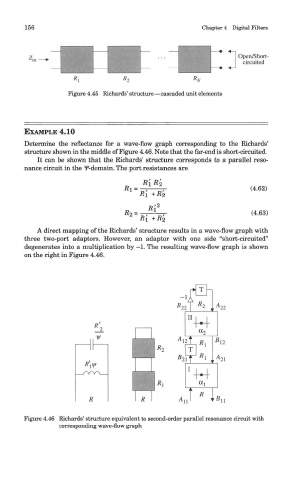
Determine the reflectance for a wave-flow graph corresponding to the Richards'
structure shown in the middle of Figure 4.46. Note that the far-end is short-circuited.
It can be shown that the Richards' structure corresponds to a parallel reso-
nance circuit in the f-domain. The port resistances are
A direct mapping of the Richards' structure results in a wave-flow graph with
three two-port adaptors. However, an adaptor with one side "short-circuited"
degenerates into a multiplication by -1. The resulting wave-flow graph is shown
on the right in Figure 4.46.
Figure 4.46 Richards' structure equivalent to second-order parallel resonance circuit with
corresponding wave-flow graph