
Page 168 - DSP Integrated Circuits
P. 168
4.17 Ladder Wave Digital Filters 153
Hence, Si must be made very small to obtain a large attenuation in the stopband
of the complementary output. Further, we have
Hence, the reflection coefficient is p = 82 and
4.16.2 Sensitivity
It can be shown that the deviation in the passband for the doubly terminated ref-
erence filter containing only transmission lines is
where £ is the tolerance of the characteristic impedances of the unit elements.
Equation (4.54) indicates that the deviation is larger close to the band edges,
where the group delay is larger. Cauer and Chebyshev II filters have smaller
group delays than Butterworth and Chebyshev I filters. A more important obser-
vation is that the deviation (sensitivity) becomes smaller if the filter is designed
such that the complementary magnitude function, I H c I max - p, is small in the
passband. This implies that the ripple in the normal magnitude function, I H I , is
small in the passband. Hence, a filter with 3 dB ripple in the passband is more
sensitive than a filter with only 0.01 dB! If the passband ripple is decreased, the
filter order may have to be increased, but the filter becomes less sensitive to com-
ponent errors. Thus, a trade-off between increased filter order and reduced sensi-
tivity can be made.
4.17 LADDER WAVE DIGITAL FILTERS
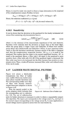
Figure 4.41 shows a third-order
transmission line filter of ladder
type. Ladder filters can realize mini-
mum phase transfer functions only.
The corresponding ladder wave digi-
tal filter with directly intercon-
nected three-port adaptors is shown
in Figure 4.42.
Note the special symbol in the
series adaptors which indicates that Figure 4.41 Reference filter of ladder type
the corresponding port is reflection-
free [10]. The use of reflection-free
ports for ladder structures is necessary in order to obtain a sequentially comput-
able algorithm. The input ai(n) corresponds to the voltage source Vi n, and b^(n) is
the normal output corresponding to the voltage across #5. In some applications a
second voltage source is placed in series with the load resistor R&.