
Page 170 - DSP Integrated Circuits
P. 170
4.18 Lattice Wave Digital Filters 155
After elimination of voltages and currents we get
where
and
and
In practice, the impedances Z\ and Z^ are pure reactances. Hence, the corre-
sponding reflectances, S\ and 82, are allpass functions. A lowpass lattice filter cor-
responds to a symmetric ladder structure and the impedances Z\ and Z-% can be
derived from the ladder structure using Bartlett's theorem T24, 301.
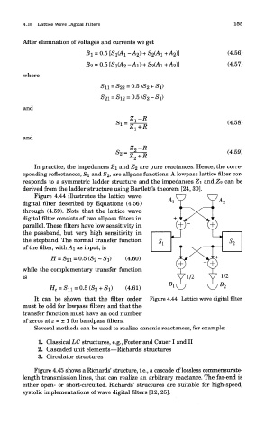
Figure 4.44 illustrates the lattice wave
digital filter described by Equations (4.56)
through (4.59). Note that the lattice wave
digital filter consists of two allpass filters in
parallel. These filters have low sensitivity in
the passband, but very high sensitivity in
the stopband. The normal transfer function
of the filter, with AI as input, is
while the complementary transfer function
is
It can be shown that the filter order Figure 4.44 Lattice wave digital filter
must be odd for lowpass filters and that the
transfer function must have an odd number
of zeros at z = ± 1 for bandpass filters.
Several methods can be used to realize canonic reactances, for example:
1. Classical LC structures, e.g., Foster and Cauer I and II
2. Cascaded unit elements—Richards' structures
3. Circulator structures
Figure 4.45 shows a Richards' structure, i.e., a cascade of lossless commensurate-
length transmission lines, that can realize an arbitrary reactance. The far-end is
either open- or short-circuited. Richards' structures are suitable for high-speed,
systolic implementations of wave digital filters [12, 25].