
Page 445 - Decision Making Applications in Modern Power Systems
P. 445
404 Decision Making Applications in Modern Power Systems
56
Conventional scheme
54
Proposed DSM scheme
52 Desired
State of charge (%) 50
48
46
44
42
40
0:00 4:00 8:00 12:00 16:00 20:00 24:00
Time (h)
FIGURE 15.7 State of charge of the battery bank.
Conventional scheme
Proposed DSM scheme
1
(A)
0
1
(B)
Control signal 0 1 (C)
0
1
(D)
0
0:00 4:00 8:00 12:00 16:00 20:00 24:00
Time (h)
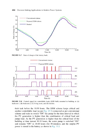
FIGURE 15.8 Control signal for controllable loads (LED bulb) mounted in building at (A)
bedroom-1, (B) bedroom-2, (C) living room, and (D) kitchen.
their task before the 10:50 hours. The DSM scheme keeps critical and
another controllable load (as per Fig. 15.7) connected as per conventional
scheme and waits to switch “ON” the pump for the time interval in which
the PV generation is higher than the combination of critical load and
pump load. As the PV generation is higher than the critical load of the
building at time instant 10:10 hours, the water pump is switched “ON”
and remains “ON” to 10:40 hours (for 30 minutes), and the surplus PV
power is stored in the battery as shown in Fig. 15.5.