
Page 163 - Defrosting for Air Source Heat Pump
P. 163
Frosting evenness coefficient 157
manual adjustments oriented by the tube surface temperature at the exit of each circuit.
Thereafter, the valves were still randomly adjusted to make the tube surface temper-
ature at the exit of each circuit the same during frosting. Finally, a higher FEC could be
reached, and thus this comparative study on frosting performance at different FECs
could be conducted.
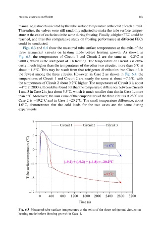
Figs. 6.3 and 6.4 show the measured tube surface temperatures at the exits of the
three refrigerant circuits on heating mode before frosting growth. As shown in
Fig. 6.3, the temperatures of Circuit 1 and Circuit 2 are the same at 9.2°Cat
2800 s, which is the start point of 1 h frosting. The temperature of Circuit 3 is obvi-
ously much higher than the temperatures of the other two circuits, more than 6°Cat
about 1.8°C. This may be result from that refrigerant distribution into Circuit 3 is
the fewest among the three circuits. However, in Case 2 as shown in Fig. 6.4, the
temperatures of Circuit 1 and Circuit 2 are nearly the same at about 7.6°C, with
the temperature of Circuit 2 about 0.2°C higher. The temperature of Circuit 3 is about
4°C at 2800 s. It could be found out that the temperature difference between Circuits
1 and 3 in Case 2 is just about 3.5°C, which is much smaller than that in Case 1, more
than 6°C. Moreover, the sum value of the temperatures of the three circuits at 2800 s in
Case 2 is 19.2°C and in Case 1 –20.2°C. The small temperature difference, about
1.0°C, demonstrates that the cold loads for the two cases are the same during
experiments.
Fig. 6.3 Measured tube surface temperatures at the exits of the three refrigerant circuits on
heating mode before frosting growth in Case 1.