
Page 168 - Defrosting for Air Source Heat Pump
P. 168
162 Defrosting for Air Source Heat Pump
9.5
Case 1 Case 2
9.0
Air temperature difference ( o C) 8.0
8.5
7.5
7.0
6.5
6.0
5.5
5.0
0 500 1000 1500 2000 2500 3000 3500 4000
Time (s)
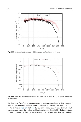
Fig. 6.10 Measured air temperature difference during frosting in two cases.
–6
Case 1 Case 2
–8
Tube surface temperature ( o C) –12
–10
–14
–16
–18
–20
–22
0 500 1000 1500 2000 2500 3000 3500 4000
Time (s)
Fig. 6.11 Measured tube surface temperatures at the exit of the outdoor coil during frosting in
the two cases.
2 a little less. Therefore, it is demonstrated that the measured tube surface tempera-
tures at the exits of the three refrigerant circuits during frosting could reflect the FEC.
As shown in Figs. 6.8 and 6.9, the measured refrigerant volume flow rate and
pressure drop across the outdoor coil kept steady from 0 s to 2500 s during frosting.
However, 2500 s into frosting, the refrigerant volume flow rate decreased and the