
Page 172 - Defrosting for Air Source Heat Pump
P. 172
166 Defrosting for Air Source Heat Pump
Table 6.2 Results of the three experimental cases
Item Parameter Case 1 Case 2 Case 3
1 Melted frost 301 g 280 g 288 g
collected from
Circuit 1
2 Melted frost 316 g 309 g 305 g
collected from
Circuit 2
3 Melted frost 261 g 305 g 295 g
collected from
Circuit 3
4 FEC 82.6% 90.6% 96.6%
5 Total mass of 878 g 894 g 881 g
melted frost
collected
6 Results shown in Figs. 6.14, 6.15, Figs. 6.14, 6.16, Figs. 6.14,
6.18, 6.21–6.24 6.19, 6.21–6.24 6.17,
6.20–6.24
6.3.2 Experimental results
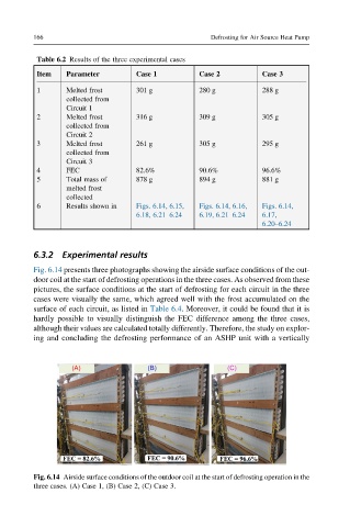
Fig. 6.14 presents three photographs showing the airside surface conditions of the out-
door coil at the start of defrosting operations in the three cases. As observed from these
pictures, the surface conditions at the start of defrosting for each circuit in the three
cases were visually the same, which agreed well with the frost accumulated on the
surface of each circuit, as listed in Table 6.4. Moreover, it could be found that it is
hardly possible to visually distinguish the FEC difference among the three cases,
although their values are calculated totally differently. Therefore, the study on explor-
ing and concluding the defrosting performance of an ASHP unit with a vertically
Fig. 6.14 Airside surface conditions of the outdoor coil at the start of defrosting operation in the
three cases. (A) Case 1, (B) Case 2, (C) Case 3.