
Page 231 - Defrosting for Air Source Heat Pump
P. 231
226 Defrosting for Air Source Heat Pump
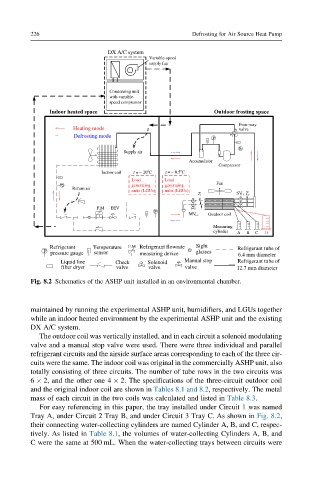
Fig. 8.2 Schematics of the ASHP unit installed in an environmental chamber.
maintained by running the experimental ASHP unit, humidifiers, and LGUs together
while an indoor heated environment by the experimental ASHP unit and the existing
DX A/C system.
The outdoor coil was vertically installed, and in each circuit a solenoid modulating
valve and a manual stop valve were used. There were three individual and parallel
refrigerant circuits and the airside surface areas corresponding to each of the three cir-
cuits were the same. The indoor coil was original in the commercially ASHP unit, also
totally consisting of three circuits. The number of tube rows in the two circuits was
6 2, and the other one 4 2. The specifications of the three-circuit outdoor coil
and the original indoor coil are shown in Tables 8.1 and 8.2, respectively. The metal
mass of each circuit in the two coils was calculated and listed in Table 8.3.
For easy referencing in this paper, the tray installed under Circuit 1 was named
Tray A, under Circuit 2 Tray B, and under Circuit 3 Tray C. As shown in Fig. 8.2,
their connecting water-collecting cylinders are named Cylinder A, B, and C, respec-
tively. As listed in Table 8.1, the volumes of water-collecting Cylinders A, B, and
C were the same at 500 mL. When the water-collecting trays between circuits were