
Page 234 - Defrosting for Air Source Heat Pump
P. 234
Energy transfer during defrosting 229
Then, the total mass of vaporized water, m v , was expressed by,
(8.5)
m v ¼ m f m m ¼ m f m cf m rw
in which m cf is the total mass of the melted frost collected in the cylinders, and m rw the
total mass of retained water.
In Eqs. (8.1), (8.2), the energy consumed on melting frost and vaporizing retained
water, Q m and Q v , were evaluated by:
(8.6)
Q m ¼ m f L sf
Q v ¼ m v L v (8.7)
where m f and m v are the total mass of the frost accumulated over the outdoor coil sur-
face and the total mass of vaporized water, and L sf and L v the latent heat of frost melt-
ing and water vaporization, respectively.
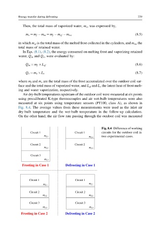
Air dry-bulb temperatures upstream of the outdoor coil were measured at six points
using precalibrated K-type thermocouples and air wet-bulb temperatures were also
measured at six points using temperature sensors (PT100, class A), as shown in
Fig. 8.4. The average values from these measurements were used as the inlet air
dry-bulb temperature and the wet-bulb temperature in the follow-up calculation.
On the other hand, the air flow rate passing through the outdoor coil was measured
Fig. 8.4 Difference of working
Circuit 1 Circuit 1 circuits for the outdoor coil in
m f,1 two experimental cases.
m f,1
Circuit 2 Circuit 2
m f,2 m f,2
Circuit 3
m f,3
Frosting in Case 1 Defrosting in Case 1
Circuit 1 Circuit 1
m f,1
m f,1
Circuit 2 Circuit 2
m f,2 m f,2
Circuit 3 Circuit 3
m f,3 m f,3
Frosting in Case 2 Defrosting in Case 2