
Page 233 - Defrosting for Air Source Heat Pump
P. 233
228 Defrosting for Air Source Heat Pump
Table 8.3 Calculated metal mass of indoor coil and outdoor coil
Item Parameter Value Unit
1 Tube mass of indoor coil 2116 g
2 Tube mass of each circuit of outdoor coil 533 g
3 Fin mass of indoor coil 380 g
4 Fin mass of each circuit of outdoor coil 477 g
5 Total mass of indoor coil 2496 g
6 Total mass of each circuit of outdoor coil 1010 g
Water collecting tray Melted frost
Circuit 1
R1 Refrigerant (Liquid)
(Vapor) Circuit 2 exit
Refrigerant entrance R2 Circuit 3
R3 Air temperature sensor
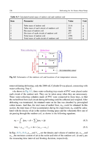
Fig. 8.3 Schematics of the outdoor coil and locations of air temperature sensors.
removed during defrosting, only the 2000 mL Cylinder D was placed, connecting with
water-collecting Tray C.
>As shown in Fig. 8.3, three water-collecting trays made of PVC were placed under
each circuit of the outdoor unit. They can be taken away when they are unnecessary.
Three water-collecting cylinders made of PVC were connected to these trays, so that
the melted frost from each circuit during defrosting could be collected and weighed. After
defrosting was terminated, the retained water on the fins was absorbed by preweighed
cotton tissues. And thus, the total mass of melted frost, m m , could be obtained. In this
section, the total mass of frost accumulation during the experiment, m f , could be calcu-
lated with the density of air in the outdoor frosting space and the volumetric flow rate of
air passing through the outdoor coil, as shown in the following equations.
t f
Z
X
m f ¼ Δm f dt ¼ Δm f Δt (8.3)
0
Δm f ¼ ρ V o,a Δt ω o,o ω o,i Þ (8.4)
ð
o,a
In Eqs. (8.3), (8.4), ρ o, a and V o, a are the density and volume of outdoor air, ω o, o and
ω o, i the moisture content of air at the outlet and inlet of the outdoor coil. Δt and t f are
the measuring time interval and frosting duration, respectively.