
Page 311 - Defrosting for Air Source Heat Pump
P. 311
306 Defrosting for Air Source Heat Pump
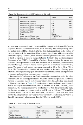
Table 10.1 Parameters of the ASHP unit used in this study
Item Parameters Value Unit
1 Rated cooling capacity 5.2 kW
2 Rated heating capacity 6.5 kW
3 Rated cooling power consumption 1600 kW
4 Rated heating power consumption 1840 kW
5 Rated cooling COP 3.25 –
6 Rated heating COP 3.53 –
7 Brand Daikin –
8 Model name of indoor unit FTXD50FVM –
9 Total price in Harbin, China $1200 USD
accumulation on the surface of a circuit could be changed, and thus the FEC can be
improved. In addition, under each circuit, water-collecting trays were placed by which
the melted frost could be collected. After the frost that accumulated on the surface of
each circuit melted, the water flowed into a measuring cylinder, which contacted the
corresponding tray. And thus, these frosts could be weighed and calculated. With this
method, as reported in previous energy studies [2–4], the frosting and defrosting per-
formances of an ASHP unit could be effectively improved after the valves were
installed. The experimental ASHP unit was installed in an existing environmental
chamber having a simulated heated indoor space and a simulated outdoor frosting
space. The sizes of both spaces were each measured at 3.8 m (L) 3.8 m (W)
2.8 m (H). The three-circuit outdoor coil was installed in the outdoor frosting space,
where the frosting/defrosting cycle operations were carried out. Detailed experimental
procedures and conditions were previously reported.
In a frosting/defrosting cycle, the frosting operation came out first. After the valves
were installed, the frosting performance would be effectively optimized. Therefore,
frosting experiments should be first undertaken before the defrosting experiments
in this study. As listed in Table 10.2, two frosting experimental cases were designed.
Valves and trays were both installed, and thus different FECs, FEC 1 and FEC 2 , could
be reached. The frosting duration was fixed at 60 min. With this experimental study,
the frosting operating performances of an ASHP unit at different FECs could be
obtained. Valves in Case F1 were fully open, and the FEC 1 was less than 100%
due to the refrigerant and air being unevenly distributed. Differently, the valves in
Case F2 were evenly adjusted, and thus the FEC 2 was nearly 100%.
Table 10.2 Two frosting experimental cases
Case No. Case F1 Case F2
Valves (Status) With (Fully open) With (Evenly adjusted)
FEC FEC 1 (<90%) FEC 2 (90% 100%)
Frosting duration 60 min 60 min
Condition shown in Fig. 10.2 (A) (B)