
Page 65 - Defrosting for Air Source Heat Pump
P. 65
56 Defrosting for Air Source Heat Pump
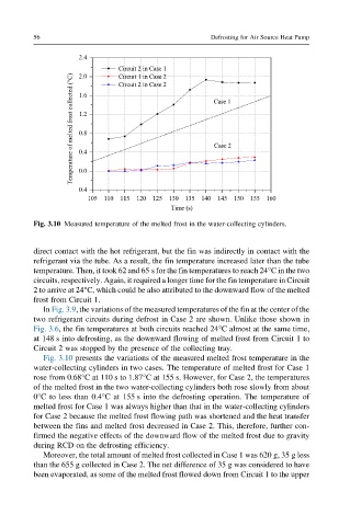
Fig. 3.10 Measured temperature of the melted frost in the water-collecting cylinders.
direct contact with the hot refrigerant, but the fin was indirectly in contact with the
refrigerant via the tube. As a result, the fin temperature increased later than the tube
temperature. Then, it took 62 and 65 s for the fin temperatures to reach 24°C in the two
circuits, respectively. Again, it required a longer time for the fin temperature in Circuit
2 to arrive at 24°C, which could be also attributed to the downward flow of the melted
frost from Circuit 1.
In Fig. 3.9, the variations of the measured temperatures of the fin at the center of the
two refrigerant circuits during defrost in Case 2 are shown. Unlike those shown in
Fig. 3.6, the fin temperatures at both circuits reached 24°C almost at the same time,
at 148 s into defrosting, as the downward flowing of melted frost from Circuit 1 to
Circuit 2 was stopped by the presence of the collecting tray.
Fig. 3.10 presents the variations of the measured melted frost temperature in the
water-collecting cylinders in two cases. The temperature of melted frost for Case 1
rose from 0.68°C at 110 s to 1.87°C at 155 s. However, for Case 2, the temperatures
of the melted frost in the two water-collecting cylinders both rose slowly from about
0°C to less than 0.4°C at 155 s into the defrosting operation. The temperature of
melted frost for Case 1 was always higher than that in the water-collecting cylinders
for Case 2 because the melted frost flowing path was shortened and the heat transfer
between the fins and melted frost decreased in Case 2. This, therefore, further con-
firmed the negative effects of the downward flow of the melted frost due to gravity
during RCD on the defrosting efficiency.
Moreover, the total amount of melted frost collected in Case 1 was 620 g, 35 g less
than the 655 g collected in Case 2. The net difference of 35 g was considered to have
been evaporated, as some of the melted frost flowed down from Circuit 1 to the upper