
Page 75 - Defrosting for Air Source Heat Pump
P. 75
66 Defrosting for Air Source Heat Pump
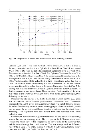
Fig. 3.19 Temperatures of melted frost collected in the water-collecting cylinders.
Cylinder C, in Case 1, rose from 0.3°C at 130 s to about 1.6°C at 195 s. In Case 2,
the temperature of the melted frost in Cylinder A, collected from Circuit 1, was around
0°C at 130 s to 150 s into the defrosting operation and rose to about 0.15°C at 195 s.
The temperature of melted frost from Circuit 3 in Cylinder C increased from 0.4°Cat
130 s to 1.2°C at 195 s. However, in Case 3, the temperatures of the melted frost in the
three cylinders, that is, A, B, and C, all rose slowly from about 0°C to less than 0.2°Cat
195 s. The temperature of the melted frost in Case 1 was always higher than that in
Case 3 because the melted frost flowing path was shortened so that the heat transfer
between the fins and the melted frost was decreased. On the other hand, in Case 2, the
flowing path of the melted frost collected in Cylinder A was half that in Cylinder C, so
that its temperature was always lower. These, therefore, further confirmed the nega-
tive effects of the downward flowing of melted frost due to gravity during RCD on
defrosting performance.
Moreover, the total amount of melted frost collected in Case 1 was 921 g, 22 g less
than that collected in Case 2 and 48 g less than that collected in Case 3. The net dif-
ferences of 22 g and 48 g were considered to have been evaporated. This was because
the melted frost flowing down was heated by the upper part of the down circuits, which
was warmer as the hot refrigerant flowed from top to bottom within the circuit during
defrosting. This explained why less melted frost was collected with fewer
collecting trays.
Furthermore, downward flowing of the melted frost not only delayed the defrosting
process, but also led to energy waste. The energy used for RCD comes from three
sources: the power input to the compressor, the power input to the indoor air fan,
and the thermal energy from the indoor air. The total energy used for defrosting
was 727 kJ in Case 1, but 652 kJ in Case 3, or 10.4% less. In Case 2, the total energy
consumed was 683 kJ, or 6.05% less than that in Case 1.