
Page 107 - Design and Operation of Heat Exchangers and their Networks
P. 107
Steady-state characteristics of heat exchangers 95
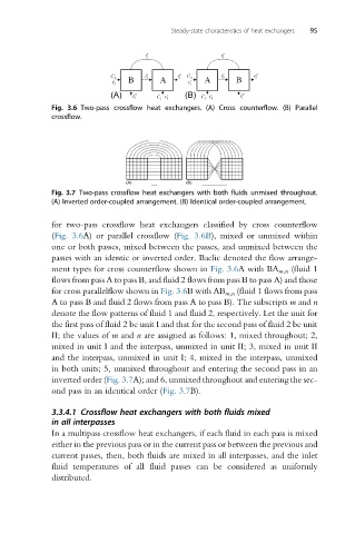
Fig. 3.6 Two-pass crossflow heat exchangers. (A) Cross counterflow. (B) Parallel
crossflow.
Fig. 3.7 Two-pass crossflow heat exchangers with both fluids unmixed throughout.
(A) Inverted order-coupled arrangement. (B) Identical order-coupled arrangement.
for two-pass crossflow heat exchangers classified by cross counterflow
(Fig. 3.6A) or parallel crossflow (Fig. 3.6B), mixed or unmixed within
one or both passes, mixed between the passes, and unmixed between the
passes with an identic or inverted order. Baclic denoted the flow arrange-
ment types for cross counterflow shown in Fig. 3.6A with BA m,n (fluid 1
flows from pass A to pass B, and fluid 2 flows from pass B to pass A) and those
for cross parallelflow shown in Fig. 3.6B with AB m,n (fluid 1 flows from pass
A to pass B and fluid 2 flows from pass A to pass B). The subscripts m and n
denote the flow patterns of fluid 1 and fluid 2, respectively. Let the unit for
the first pass of fluid 2 be unit I and that for the second pass of fluid 2 be unit
II; the values of m and n are assigned as follows: 1, mixed throughout; 2,
mixed in unit I and the interpass, unmixed in unit II; 3, mixed in unit II
and the interpass, unmixed in unit I; 4, mixed in the interpass, unmixed
in both units; 5, unmixed throughout and entering the second pass in an
inverted order (Fig. 3.7A); and 6, unmixed throughout and entering the sec-
ond pass in an identical order (Fig. 3.7B).
3.3.4.1 Crossflow heat exchangers with both fluids mixed
in all interpasses
In a multipass crossflow heat exchangers, if each fluid in each pass is mixed
either in the previous pass or in the current pass or between the previous and
current passes, then, both fluids are mixed in all interpasses, and the inlet
fluid temperatures of all fluid passes can be considered as uniformly
distributed.