
Page 124 - Design and Operation of Heat Exchangers and their Networks
P. 124
112 Design and operation of heat exchangers and their networks
3.4.1 Mathematical model
The thermal calculation of spiral heat exchangers has been analyzed theoret-
ically, experimentally, and numerically by many researchers (Baird et al.,
1958; Chowdhury et al., 1985; Picon-Nunez et al., 2007; Rajavel and
Saravanan, 2008; Sathiyan et al., 2010; Kaman et al., 2017). A systematic
theoretical work has been contributed by Bes (1978, 2001) and Bes and
Roetzel (1992a, 1992b, 1993, 1998) and is introduced as follows.
Bes and Roetzel (1992a) treated the spiral heat exchanger with the spi-
ral of Archimedes. A spiral heat exchanger can usually be divided into
three regions: the innermost region where heat is transferred only through
one wall; the middle region (referred to as bulk part) with turns, which
usually occupies the main space of the exchanger and performs the main
duty of the exchanger; and the outmost region, where heat is transported
again through one wall only (i.e., the outside wall of the spiral heat
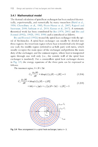
exchanger is insulated). For a counterflow spiral heat exchanger shown
in Fig. 3.9, the energy equations of the three parts can be expressed as
follows:
The innermost region,0<θ<2π:
_ dt h θðÞ
C h + khrφ rðÞ t h θðÞ t c θðÞ½ ¼ 0 (3.208)
dθ
_ dt c θðÞ
C c + khrφ rðÞ t h θðÞ t c θðÞ½
dθ (3.209)
ð
ð
+ kh r + s c Þφ r + s c Þ t h θ +2πð½ Þ t c θðÞ ¼ 0
.
t h,out , C h
.
r t c,in , C c
s q
r 0
t h,in
t c,out
Fig. 3.9 Flow arrangement in a spiral heat exchanger, turns n¼3.