
Page 122 - Design and Operation of Heat Exchangers and their Networks
P. 122
110 Design and operation of heat exchangers and their networks
The ε-NTU relationship given in Table 5 of Baclic (1990) for AB 2,6 has a
sign error. It should be the same as that for AB 2,6 , as is checked by the
numerical calculation. The MatLab code “Examples for two-pass crossflow
heat exchangers (MatLab code)” for the calculation of the previous examples
together with the numerical procedure can be found in the appendix.
3.3.4.5 Multipass crossflow heat exchangers
The fluid temperature distributions in a multipass crossflow heat exchanger
can be obtained by means of finite difference method. A numerical proce-
dure “Examples for two-pass crossflow heat exchangers (MatLab code)” for
such calculations is provided in the appendix.
1
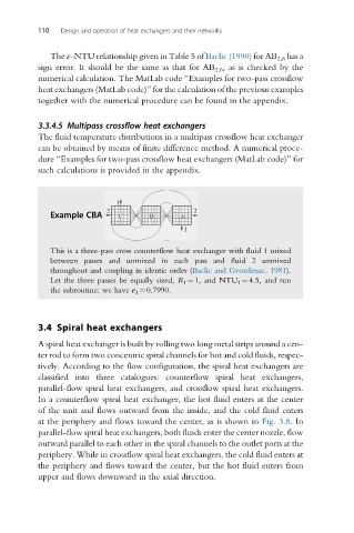
Example CBA 2 C B A 2
1
This is a three-pass cross counterflow heat exchanger with fluid 1 mixed
between passes and unmixed in each pass and fluid 2 unmixed
throughout and coupling in identic order (Baclic and Gvozdenac, 1981).
Let the three passes be equally sized, R 1 ¼1, and NTU 1 ¼4.5, and run
the subroutine; we have ε 1 ¼0.7990.
3.4 Spiral heat exchangers
A spiral heat exchanger is built by rolling two long metal strips around a cen-
ter rod to form two concentric spiral channels for hot and cold fluids, respec-
tively. According to the flow configuration, the spiral heat exchangers are
classified into three catalogues: counterflow spiral heat exchangers,
parallel-flow spiral heat exchangers, and crossflow spiral heat exchangers.
In a counterflow spiral heat exchanger, the hot fluid enters at the center
of the unit and flows outward from the inside, and the cold fluid enters
at the periphery and flows toward the center, as is shown in Fig. 3.8.In
parallel-flow spiral heat exchangers, both fluids enter the center nozzle, flow
outward parallel to each other in the spiral channels to the outlet ports at the
periphery. While in crossflow spiral heat exchangers, the cold fluid enters at
the periphery and flows toward the center, but the hot fluid enters from
upper and flows downward in the axial direction.